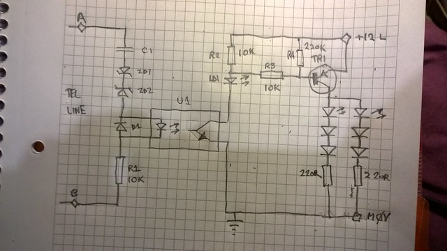
a hybrid of analogue and digital circuitry - an analogue telephone circuit (from my PABX but equivalent to a standard phone line) is connected to the interface board; which has to deal with the 80-100V ringing voltage which is clamped by zener diodes and sent to an optoisolator; this feeds a transistor switch that can switch about 100mA of LEDs.
As well as the LEDs the signal is sent to a Raspberry Pi running pirsclockful (with the GPIO inputs suitably protected by optoisolators) I build and maintain telephone systems and other signalling.control/alarm kit for my day job; so have plenty of spare telecom related bits and pieces")
this is the interface circuit (I used 10V zeners and a CNY17 opto - you may need to vary the rating of the zeners depending on what your local ringing voltage is. It is also best not to hold on to the phone wires or any bit of the circuit connected to the telecom network when it is ringing )
I am too old/dumb to work the computer based circuit diagram software (trying to learn it but I find it quicker sometimes to do things the old way)
https://www.flickr.com/photos/rtnvfrmedia/16365616321/
a link to the python based studio clock
https://github.com/Engineeringradio/pirsclockfull
As well as the LEDs the signal is sent to a Raspberry Pi running pirsclockful (with the GPIO inputs suitably protected by optoisolators) I build and maintain telephone systems and other signalling.control/alarm kit for my day job; so have plenty of spare telecom related bits and pieces
this is the interface circuit (I used 10V zeners and a CNY17 opto - you may need to vary the rating of the zeners depending on what your local ringing voltage is. It is also best not to hold on to the phone wires or any bit of the circuit connected to the telecom network when it is ringing
)I am too old/dumb to work the computer based circuit diagram software (trying to learn it but I find it quicker sometimes to do things the old way)
https://www.flickr.com/photos/rtnvfrmedia/16365616321/
a link to the python based studio clock
https://github.com/Engineeringradio/pirsclockfull